






























RCBO: Your Ultimate Protection Against Electrical Faults
RCBO: Your Ultimate Protection Against Electrical Faults
When Priya, a facilities engineer in Manchester, re-energised a refurbished office floor, one lighting circuit tripped within seconds. The team replaced the protective device, yet the trip returned when a compact power supply was connected. Tracing the neutral, measuring leakage and checking the prospective fault current reversed the assumption: the device was not simply defective; the circuit had been specified without matching residual-current behaviour, overcurrent duty and neutral routing.
Summary: An RCBO (residual-current circuit-breaker with overcurrent protection) combines two protective functions in one device. It should disconnect a circuit for overload or short circuit and for dangerous current imbalance, but only when its pole arrangement, residual-current type, rating and breaking capacity match the installation. IEC 61009-1 is the key product standard for household and similar RCBOs; installation rules such as IEC 60364-4-41 and local wiring regulations still govern the complete system. Specify from measured design data, verify the exact model’s evidence and commission the installed circuit.
For buyers, the attraction is practical: each final circuit can have dedicated protection, so a fault on a socket or charger need not remove power from every circuit. The trade-off is that an RCBO is not a universal safety licence. Correct earthing, conductor sizing, discrimination, environmental suitability and documented testing remain essential.
What an RCBO detects—and what it cannot fix
The overcurrent section responds to sustained overload and high-current short circuits. Its thermal element deals with heating from excess current, while a magnetic element reacts rapidly to a severe fault; the exact time-current curve must be selected for the load and cable. The residual-current section compares the current leaving on live conductors with the current returning. A difference indicates leakage through protective earth, a person or unintended path, and the device opens the circuit.
Residual sensitivity is normally stated as IΔn, such as 30 mA for additional personnel protection where required by local rules. That number is a trip threshold under specified test conditions, not a promise that a person is safe in every contact scenario. An RCBO cannot correct a missing protective conductor, a shared neutral, poor insulation or an incorrectly wired bypass; those defects must be found and repaired.

Choose the residual-current waveform deliberately
Type AC devices respond to sinusoidal alternating residual current. Type A adds pulsating direct-current sensitivity and is common on circuits with modern electronic loads. Type F extends performance for certain single-phase variable-speed equipment, while Type B is designed for AC, pulsating DC and smooth DC components within its declared scope. Selection depends on the load manufacturer’s instructions and the local installation standard—not on a distributor’s generic label.
Electric-vehicle equipment illustrates the issue. A charger may include a 6 mA DC residual-current detecting device (RDC-DD), allowing a Type A arrangement where the charger documentation permits it; where that function is absent, a broader device may be required. IEC 62955 covers RDC-DDs for mode 3 charging, while IEC 61851-1 covers conductive EV supply equipment. Always verify what the actual EVSE monitors and how it must be tested.
| Design question | Evidence to collect | Why it changes the choice |
|---|---|---|
| What waveform can the load produce? | Equipment manual, leakage-current data and declared RCD type | Determines Type AC, A, F, B or another permitted device |
| What is the design current and cable capacity? | Load schedule, conductor method, ambient and grouping corrections | Sets the RCBO current rating and prevents thermal overload |
| What fault current is available at the board? | Prospective short-circuit calculation or measurement | Confirms the required short-circuit breaking capacity |
| How are neutrals and phases arranged? | Single-line diagram, pole count and neutral-bar layout | Prevents nuisance trips and loss of residual-current sensing |
Ratings, curves and coordination are a package
A rating such as 16 A, 32 A or 63 A is the device’s declared current under specified conditions; it must not exceed the cable’s corrected capacity. For a continuous load, apply the project’s derating and thermal rules rather than relying on a nominal nameplate. A B, C or D tripping curve changes magnetic response to inrush; it does not increase conductor ampacity or replace a fault study.
Breaking capacity (often marked Icn or an equivalent value) describes the short-circuit current the RCBO can interrupt in the standard test sequence. Compare it with prospective fault current at the installation point and check any permitted backup or cascading arrangement. Residual selectivity also matters: upstream and downstream devices need compatible sensitivities, time delays and waveform performance so that the smallest affected circuit disconnects first.
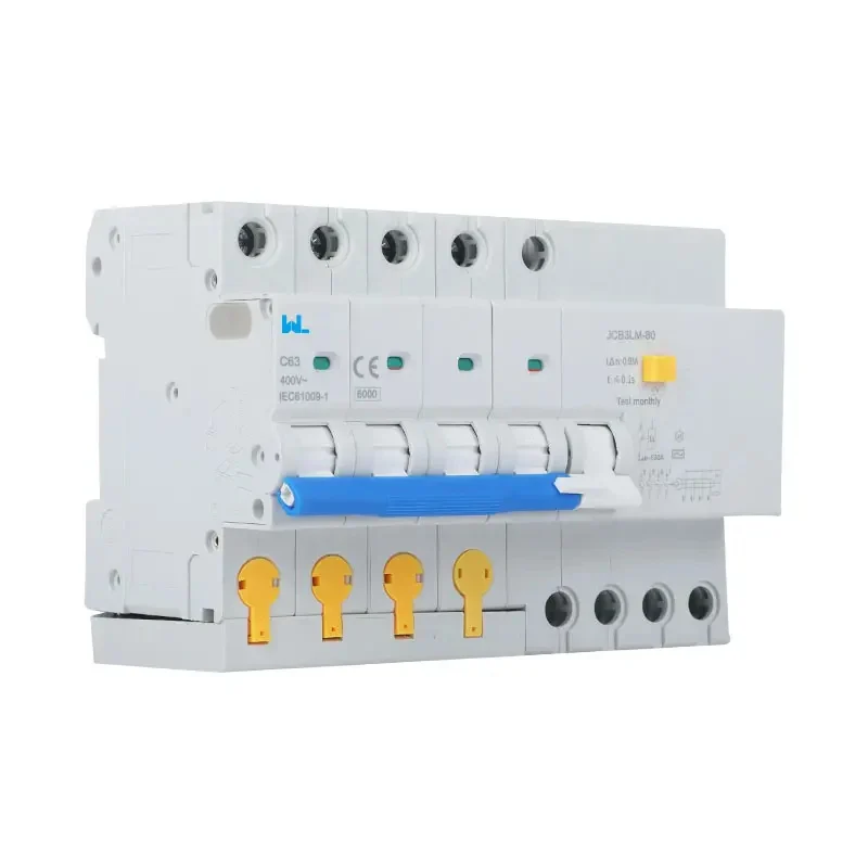
Keep every current-carrying conductor belonging to the circuit through the RCBO sensing path. A borrowed neutral, a neutral-to-earth connection downstream or a line conductor that bypasses the device can cause immediate trips or leave a circuit unprotected. For a single-phase line-and-neutral branch, a two-pole RCBO may isolate both conductors; for multi-phase systems, use the pole and neutral treatment shown in the approved design.
Installation and commissioning that stand up to audit
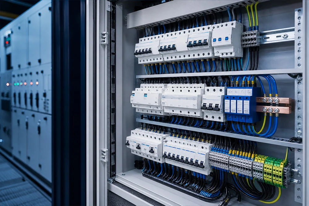
Before installation, check the DIN-rail footprint, terminal capacity, conductor preparation, torque instructions, enclosure temperature and ingress conditions. Confirm that busbars and accessories are compatible with the exact catalogue number. Label each protected circuit and leave room for safe test access; crowded boards increase maintenance time and the chance of a wiring error.
Commissioning should combine inspection with instruments appropriate to the device type. Typical checks include protective-conductor continuity, polarity, insulation resistance (with sensitive electronics isolated as instructed), earth-fault loop or prospective-fault values, residual operating current and trip time. Use a tester that supports the selected Type A, F or B waveform; the front-panel test button verifies the mechanism, not the complete installation. Record instrument identification, test mode, measured values and corrective actions.
For an RCBO that trips unexpectedly, first separate residual and overcurrent causes. Measure leakage with the load operating, inspect neutral routing and terminal tightness, and check temperature rise and inrush. Moisture, damaged cable insulation, filters in multiple devices or an unsuitable waveform can all create symptoms that a replacement device will not cure.
| Stage | Action | Record for the project file |
|---|---|---|
| Design | Calculate design current, cable capacity, fault level and residual waveform | Load schedule, calculations and equipment manuals |
| Procurement | Match poles, curve, sensitivity, breaking capacity and enclosure interface | Exact datasheet, declaration and coordination information |
| Installation | Route neutrals correctly; tighten terminals; label and photograph the board | As-built diagram, torque/inspection record and photos |
| Handover | Perform residual, insulation and fault-loop tests with suitable instruments | Signed results, tester details and maintenance interval |
Standards, compliance and market scope
IEC 61009-1 specifies requirements and test methods for RCBOs for household and similar uses. It is a product standard, not an installation certificate. IEC 60364-4-41 addresses protection against electric shock, and IEC 60364-5-53 covers selection and erection of switching and protective devices; national adoptions may add rules for specific locations. For EV circuits, IEC 60364-7-722 and IEC 61851-1 add application requirements, while IEC 62955 addresses RDC-DD performance.
North American projects follow a different route; UL 943 covers ground-fault circuit-interrupter products and UL 2231-1/-2 address personnel-protection systems for EV supply circuits. A CE, UL, TÜV or other mark is meaningful only when the certificate scope, model and destination market match the supplied device. Unsupported certification claims can delay approvals, trigger rework or expose an OEM to contractual and regulatory risk.
How W9 can support a documented specification
Zhejiang W9 Group Technology Co., Ltd., established in 2020, describes a low-voltage protection portfolio that includes MCBs, RCCB/RCDs, RCBOs, MCCBs, SPDs and AFDDs, with OEM/ODM and testing support. For a sourcing programme, treat that capability as a starting point: provide the single-line diagram, target market, load data and required standard, then request model-specific drawings, declarations and test records. The JC3LE four-pole electromagnetic RCBO listing can be reviewed as a reference, not as a universal approval.
Frequently asked questions
Is an RCBO better than an MCB and RCCB combination?
An RCBO combines both functions per circuit and can reduce the impact of a single final-circuit fault. An MCB plus RCCB may still suit a board’s space, selectivity or maintenance strategy. Compare total coordination, neutral arrangement and evidence rather than assuming one topology is always superior.
What causes an RCBO to trip when no appliance appears faulty?
Common causes include cumulative filter leakage, a shared neutral, moisture, insulation damage, inrush or an unsuitable residual-current type. Measure the circuit under operating conditions and inspect wiring before changing the device. A competent person should isolate dangerous faults.
Does a 30 mA RCBO protect against every electric shock?
No. A 30 mA sensitivity is an additional protection measure under defined test conditions. It cannot compensate for direct contact, missing earthing, incorrect wiring or delayed operation outside the device scope. Follow the applicable installation standard and safe-isolation procedures.
How do I select RCBO breaking capacity?
Determine prospective short-circuit current at the RCBO terminals and select a device whose declared breaking capacity meets that duty, including any approved backup arrangement. Do not use a high kA label as a substitute for calculation or coordination data.
Which tests should be recorded at handover?
Record visual inspection, protective-conductor continuity, polarity, permitted insulation tests, loop or prospective-fault values, residual trip current and trip time. Use waveform-appropriate instruments and include the tester ID, settings and remedial actions. Repeat tests after alterations.
For practical context, read what an RCBO does and review how RCBOs enhance electrical safety before finalising your schedule.
References
- International Electrotechnical Commission — IEC 61009-1, IEC 60364 series, IEC 61851-1 and IEC 62955 scopes.
- Institution of Engineering and Technology — BS 7671 guidance and electrical-installation principles.
- UL Solutions — UL 943 and UL 2231 product and personnel-protection scope.
- National Fire Protection Association — NFPA 70 context for overcurrent and ground-fault protection.
The dependable rule is simple: match the current path, fault level, waveform and test evidence as one protection system. When your project needs an RCBO schedule or OEM review, explore W9’s product catalogue and contact the team with circuit data and destination-market requirements.