



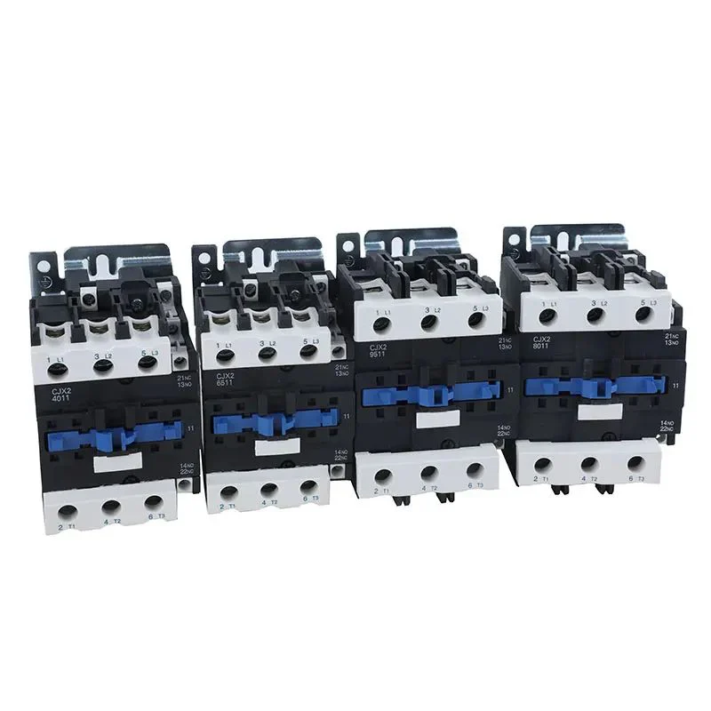





The Future of Thermal Magnetic Circuit Breakers: Advancements and Applications
A replacement feeder breaker can trip for the same reason as the original if its curve, conductor limits and load profile were never checked together. For buyers considering newer thermal-magnetic designs, the useful question is which protection functions the circuit needs and which monitoring functions the maintenance team can actually support.
Summary: A thermal magnetic circuit breaker uses thermal overload and magnetic short-circuit releases. An electronic trip unit is a different protection arrangement; adding metering or a communications accessory does not change a thermal release into an electronic one. Choose between them using the load envelope, required selectivity, fault duty and maintenance capability. Industrial breaker requirements and household breaker requirements have different scopes. Request the exact model manual, time-current curves and destination-market evidence before approving a design or replacement.
Electrification is changing duty cycles. Heat pumps, drives, battery storage and high-power chargers create sustained currents, inrush and harmonics that expose weak assumptions. The question is where thermal magnetic simplicity remains an advantage and where digital supervision earns its cost.
Thermal-Magnetic Breaker Development
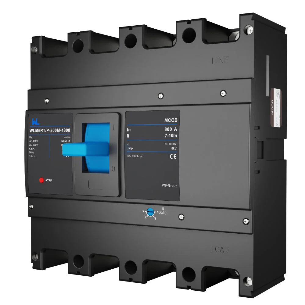
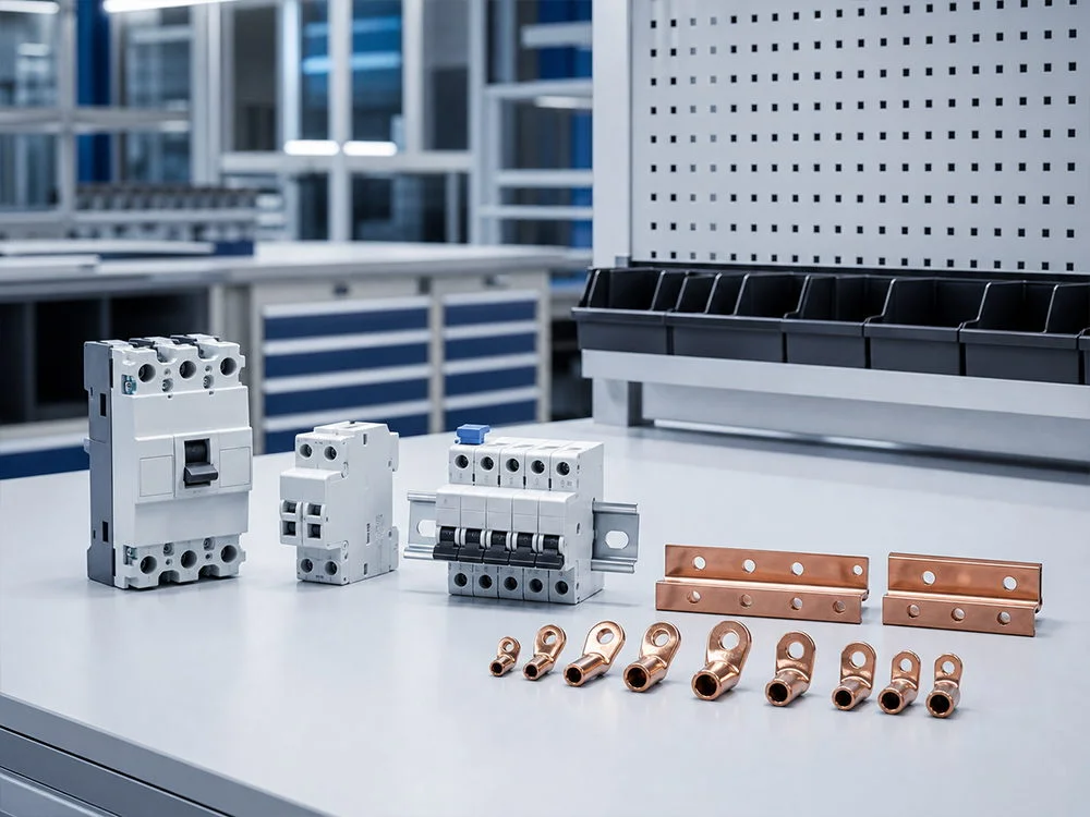
A conventional thermal magnetic circuit breaker uses two physical responses. A bimetal bends when current heats it, producing an inverse-time trip for sustained overloads. A magnetic element responds to high current almost instantly for short-circuit protection. This separation lets the breaker tolerate normal motor starting while still clearing a severe fault; the actual time-current curve must be taken from the manufacturer’s tested data. In that sense, overload protection is a thermal decision while fault clearing is predominantly magnetic.
Modern molded-case designs add adjustable dials, interchangeable accessories and improved arc chambers without changing that core physics. A qualified person should set them after checking conductor ampacity, ambient correction, enclosure temperature and the manufacturer’s instructions. A higher ampere frame is not permission to increase a setting: the weakest conductor or terminal still governs.
Electronic Trip Integration
Electronic trip units use current sensors and processing to implement the protection functions provided by that model. Some obtain energy for overcurrent protection from the measured current; separate power may still be needed for displays, communications, alarms or particular accessories. Do not assume either that loss of an auxiliary supply disables all protection or that every function remains available. Compare an electronic release with thermal-magnetic protection as a complete system, including configuration, testing and support.
Protection During Supply Loss
Ask the supplier to distinguish four outcomes when auxiliary power is absent: overcurrent tripping, local indication, alarm contacts and remote communications. Record the supply source and minimum operating conditions for each function. A blank display and an unavailable trip release are different failure states. An approved acceptance plan should verify the documented behavior using the manufacturer’s test method; disconnecting an arbitrary supply on an energized panel is not a substitute for that plan.
Use the guide to choosing the right thermal magnetic circuit breaker to structure the initial comparison, then obtain the exact manual for any electronic alternative. Keep power-loss behavior alongside the time-current study so procurement does not approve a monitoring feature while overlooking a protection dependency.
Trip Diagnostics and Service Continuity
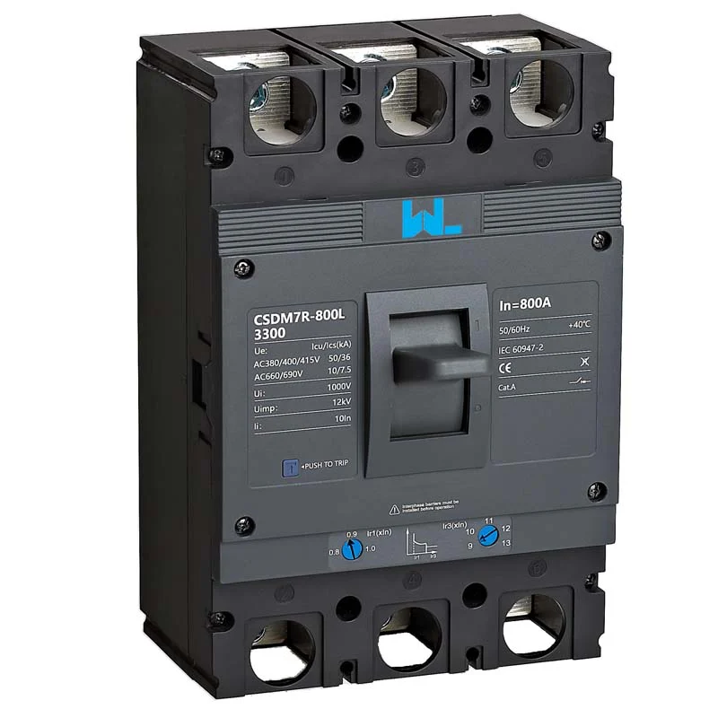
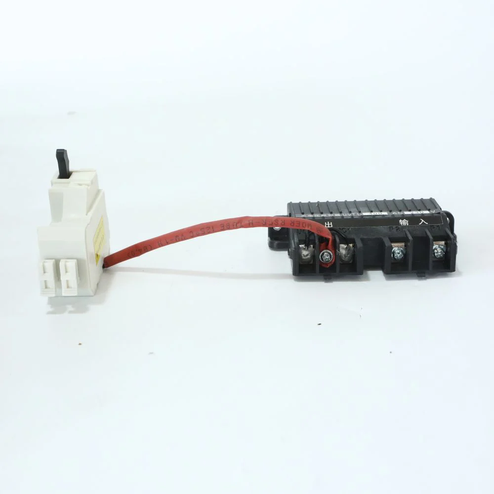
Digital accessories can timestamp trips, report cause codes and expose rising load before nuisance operation. A maintenance team may use a Modbus or manufacturer-specific gateway to trend phase current, but communications do not replace a local trip mechanism or safe isolation procedure. Treat every data point as an aid to inspection, not proof that a conductor, connection or busbar is healthy. Alarms should prompt an overload protection review before someone simply raises the pickup setting.
Coordination remains the engineering anchor. Plot upstream and downstream time-current curves at the actual voltage and fault level; verify short-circuit withstand and let-through energy for the equipment. A selective scheme may require intentional short-time delay upstream, while a motor branch may need a magnetic pickup that rides through starting current. IEC 60947-2 includes requirements and verification for low-voltage circuit-breakers, while the project designer still must apply the installation rules that govern cable protection and disconnection.
Illustrative calculation: Suppose a three-phase 400 V feeder is expected to carry 250 A after demand factors. If an engineer applies a 1.20 planning margin, the arithmetic is 250 A × 1.20 = 300 A. That number is only a screening value; the final rating must be checked against conductor ampacity, ambient conditions, fault current and the breaker’s continuous-current convention. If a 400 A frame has an adjustable long-time pickup, documenting why the setting is 300 A is more valuable than simply choosing the largest available frame.
| Approach | Strengths | Trade-offs to manage | Typical fit |
|---|---|---|---|
| Fixed thermal magnetic | Simple operation, no settings menu, familiar field service | Less flexibility for changing loads; limited event information | Small distribution boards and stable final circuits |
| Adjustable thermal magnetic | Better matching to feeders, motor starting and conductor limits | Settings can be changed incorrectly; coordination data is essential | Commercial feeders, OEM panels and retrofit work |
| Electronic trip unit | Configurable protection functions and optional metering or event records | Verify sensor-powered protection, auxiliary-supply needs and configuration control for the exact model | Feeders that need documented selectivity or diagnostic functions |
| Networked protection package | Remote status, alarms and maintenance workflows | Cybersecurity, interoperability and lifecycle support must be budgeted | Facilities with a mature power-management platform |
Keep a Replacement Baseline
Before releasing a substitute breaker or trip unit, compare the full catalogue reference, sensor or rating-plug basis, curve revision, fitted accessories and approved settings. The same frame size does not prove the same trip behavior. Retain the previous as-left record and obtain approval for any revised coordination limits. After a high-current interruption, follow the manufacturer’s inspection and replacement instructions rather than treating a successful reset or an Ics marking as automatic permission to return to service.
The decision rule is to preserve the protection envelope first, then restore the monitoring features. For U.S. workplace applications, OSHA 1910.303 separately requires adequate interrupting rating and coordinated circuit characteristics; it does not approve a substitute merely because the ampere label matches.
Changing Loads and Lifecycle Cost
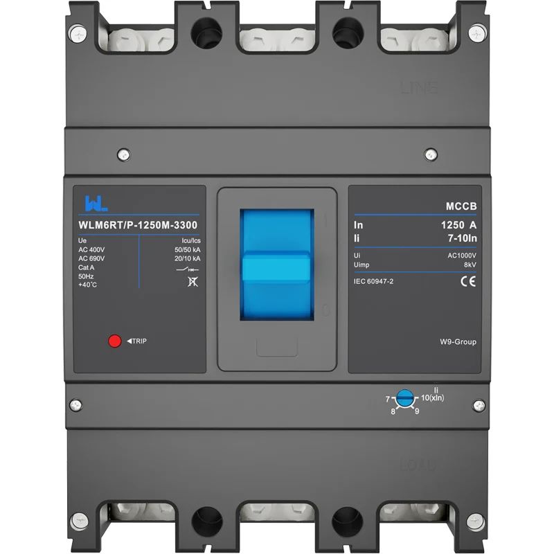
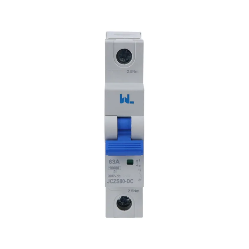
EV chargers and battery systems can shift a site from occasional peaks to long, high-utilization periods. Heat pumps add seasonal loading; inverters can alter fault-current characteristics. Specify the AC or DC topology, switching duty, ambient range and required isolation before selecting a thermal magnetic circuit breaker. For DC circuits, use a breaker explicitly tested and marked for the system voltage and polarity; an AC device is not automatically suitable.
Lifecycle cost includes engineering hours, commissioning, spares, outage exposure and safe maintenance—not just purchase price. A breaker with a lower unit cost can be expensive if a nuisance trip stops a production line or if undocumented settings force a site survey. Conversely, a networked electronic unit may not pay back in a lightly loaded warehouse. Compare the cost of one avoided diagnostic visit with the recurring cost of gateways, training and cybersecurity reviews; robust overload protection is valuable only when the site can maintain it.
For OEMs, repeatability is a value driver. Consistent terminal layouts, accessory codes and a controlled settings sheet reduce panel-build variation. Contractors should request current curves, interrupting ratings at installation voltage and a replacement procedure. Procurement teams can then compare equivalent duty rather than labels.
Market-Specific Protection Requirements
IEC 60947-2 covers circuit-breakers used in low-voltage switchgear and controlgear, generally in industrial and equipment contexts. IEC 60898-1 addresses circuit-breakers for overcurrent protection in household and similar installations by ordinary persons. UL 489 is the North American standard for molded-case circuit breakers and circuit-breaker enclosures; its construction, marking and certification pathway differ from IEC practice. NFPA 70 (the National Electrical Code) sets U.S. installation requirements, including conductor protection and working-clearance rules, but it is not a product test standard.
Always match the declaration, test report and marking to the market and end use. Do not imply UL, IEC or NFPA compliance from a catalog image alone, and do not present a test method as a universal certification. Unsupported claims can delay approvals, invalidate a panel listing or create warranty disputes. The authority having jurisdiction and the project’s contract documents determine which edition and local amendments apply.
Breaker Procurement Checks
- Define the circuit: AC or DC, system voltage, phases, frequency, neutral arrangement and continuous versus intermittent duty.
- Calculate protection inputs: design current, conductor ampacity, ambient derating, motor or charger inrush and prospective short-circuit current.
- Check coordination: obtain tested curves and verify selectivity, backup protection, let-through energy and terminal temperature limits.
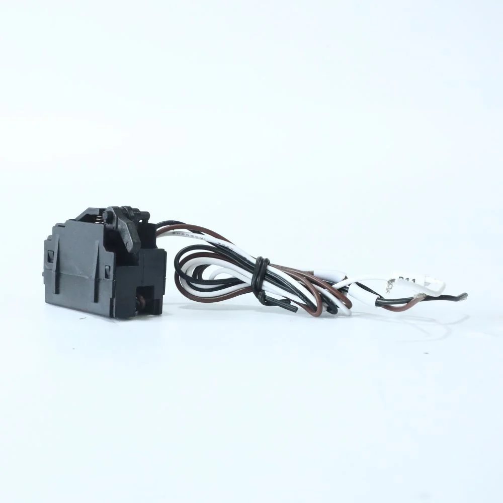
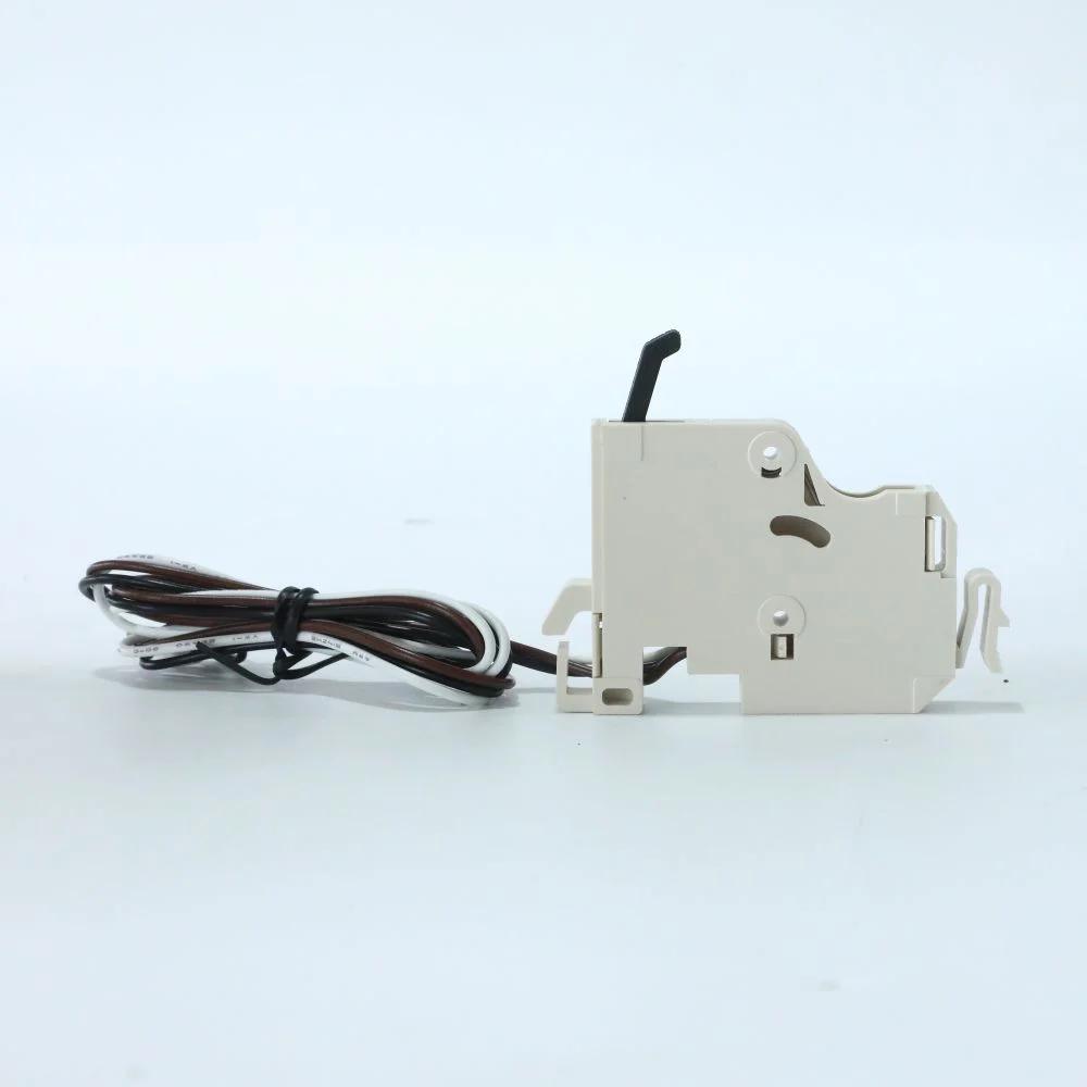
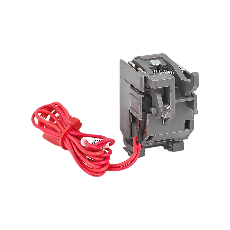
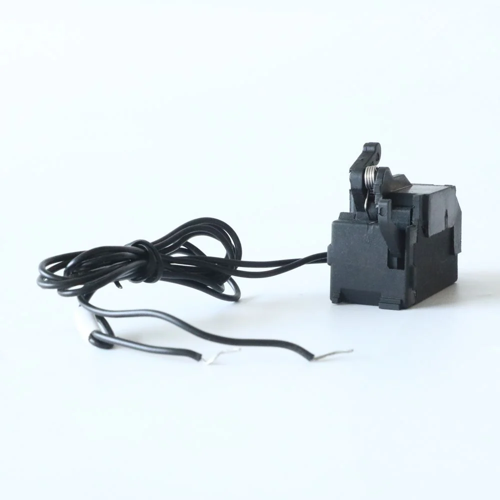
- Specify usability: choose fixed or adjustable settings, local indication, shunt/undervoltage releases, auxiliary contacts and communication only when they solve a defined task.
- Lock the lifecycle plan: require setting sheets, inspection intervals, spare references, torque values and a documented acceptance test.
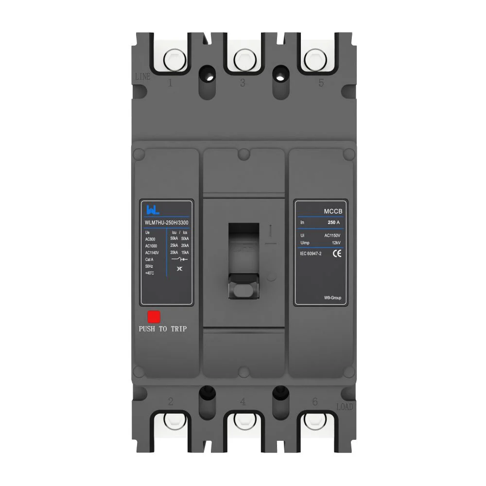
For a configurable feeder, review the WLM6RT 400 A adjustable MCCB product information as a starting point. W9 Group provides low-voltage circuit protection options for OEM, panel-builder and distribution projects; confirm the exact model, ratings, documentation and destination-market requirements before release.
| Cost driver | Evidence to request | Why it matters |
|---|---|---|
| Commissioning | Setting templates, torque values and acceptance-test instructions | Shortens startup and reduces undocumented adjustments |
| Downtime | Trip indication, spare strategy and reset/isolation procedure | Improves recovery while preserving safe work practices |
| Expansion | Accessory compatibility and frame-range documentation | Avoids panel redesign when loads or monitoring grow |
| Compliance | Applicable declarations, reports and market markings | Supports approvals and defensible procurement records |
Frequently asked questions
Are thermal magnetic circuit breakers becoming obsolete?
No. Their passive overload response and straightforward maintenance remain valuable in many distribution and OEM applications. Electronic trips are an option where measurement, selectivity or remote diagnostics outweigh added integration work.
What is the difference between IEC 60947-2 and IEC 60898-1?
IEC 60947-2 applies to low-voltage circuit-breakers in switchgear and controlgear, typically handled by skilled users. IEC 60898-1 covers overcurrent breakers for household and similar installations; confirm the intended environment before specifying either standard.
How often should overload protection settings be reviewed?
Review settings whenever loads, conductors, ambient conditions or upstream equipment change, and during the site’s planned maintenance interval. Keep a controlled record so a field adjustment can be traced to the approved coordination study.
Can an AC MCCB protect a battery circuit?
Only if the device is explicitly rated and tested for the battery system’s DC voltage, polarity, interruption duty and installation category. Otherwise select a purpose-designed DC breaker and verify the complete fault-clearing path.
Where can I compare adjustable MCCB features?
Compare the required trip functions, adjustment range and support documents against the actual feeder study. The adjustable MCCB application guide offers related selection questions; the final choice still depends on model-specific curves and installation conditions.
Authoritative references
- EEP — 6 Adjustable Tripping Settings of a Circuit Breaker. Technical explanation of setting functions; examples are not universal model settings. Accessed 16 October 2026.
- Schneider Electric — What do Icu and Ics refer to on a PowerPact breaker?. Manufacturer explanation, modified 10 May 2022; no automatic field-reuse approval. Accessed 16 October 2026.
- OSHA 29 CFR 1910.303 — General electrical requirements. U.S. workplace rules on equipment suitability, interrupting rating and coordination. Accessed 16 October 2026.
The dependable choice is the one you can explain: match the mechanism to the duty, prove coordination with tested data and preserve a record. If comparing frames, accessories or OEM configurations, browse W9’s low-voltage protection products and contact the team with voltage, load, fault-current and destination-market requirements.