






























Modular Contactors: The Unsung Heroes of Modern Electrical Systems
A lighting-control schedule can specify a contactor with a load current below its headline ampere rating and still omit the most important information: what it must make and break. LED drivers, heaters and motors present different switching duties. If that distinction is missed, the controller may be correctly programmed while the switching device is poorly matched to its task.
Quick answer: Select a modular contactor by utilization category and actual switching duty, not thermal current alone. Check load technology, inrush, operational voltage, switching frequency, coil supply, poles and the manufacturer’s application limits. IEC 61095:2023 covers household and similar electromechanical contactors and adds requirements for LED switching, including category AC-7d. IEC 60947-4-1:2023 addresses an industrial contactor and motor-starter scope. The compact or modular label does not make every device suitable for every lighting or motor load.

Contactor Switching Ratings
A contactor repeatedly connects and disconnects a load under control of its coil or operating system. Carrying current through closed contacts and making or breaking current are different tasks. Starting a motor or energising many electronic drivers can impose conditions that a resistive-load current rating does not describe.
The utilization category provides a framework for specifying the relevant load and operating conditions. Read the rated operational current at the stated voltage and category, not an isolated thermal-current value. Also distinguish mechanical endurance from electrical endurance under load; a mechanical operation count does not guarantee the same count when switching the actual circuit.
A resistive-load rating is not a universal motor or LED rating. For lighting, request the manufacturer’s supported driver loads, inrush conditions or application table. For motors, identify the starting and stopping duty and any frequent jogging or reversing. Do not invent a percentage derating when the required manufacturer data is unavailable.
Household vs Industrial Contactor Standards
IEC 61095:2023 describes household and similar electromechanical air-break contactors. Its public scope includes rated voltages up to 440 V AC between phases and category-specific operational-current limits. Those are standard-scope boundaries, not a statement that every modular contactor has the maximum values.
IEC 60947-4-1:2023 describes electromechanical contactors and starters, motor protective switching devices and other listed equipment for circuits within its stated scope. The IEC catalogue includes the March 2026 corrected version. Use the standard route applicable to the selected equipment and destination project; neither reference independently certifies a W9 model.
| Load or duty | Information to establish | Relevant evidence route | Common error |
|---|---|---|---|
| Resistive heating | Load current, voltage and switching cycle | Applicable resistive-duty rating and temperature limits | Ignoring enclosure heat and repeated operation |
| Household motor load | Starting current and supported duty | Applicable AC-7b or manufacturer application data | Using the slightly inductive-load rating without checking |
| LED driver groups | Driver technology and aggregate inrush | AC-7d or explicit manufacturer LED-load data where applicable | Selecting only from steady-state watts |
| Industrial motor control | Starting, stopping and operating frequency | Industrial utilization category and starter coordination | Treating normal running duty as repeated jogging duty |
| Capacitor switching | Capacitor-bank configuration and switching conditions | Dedicated capacitor-duty documentation | Assuming an ordinary lighting contactor is equivalent |
Contactor Coil and Control Requirements
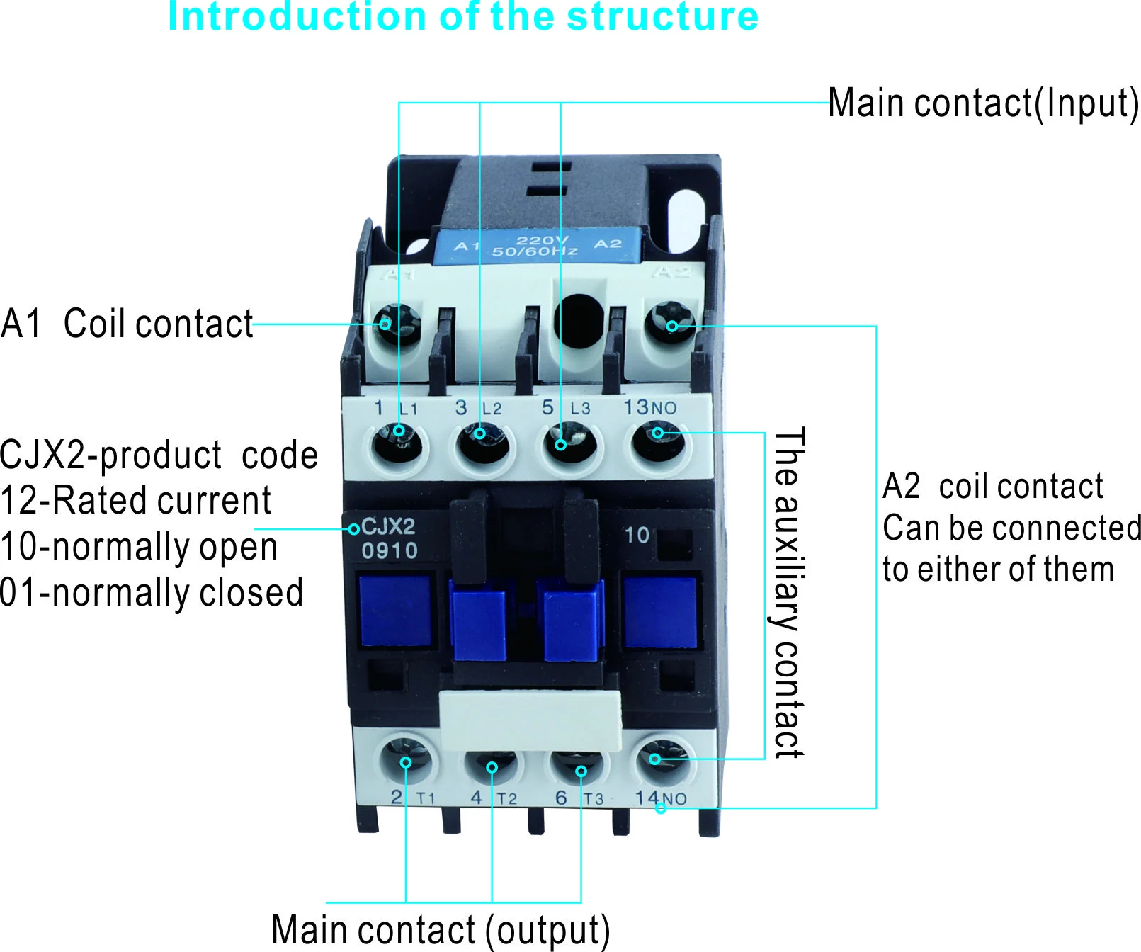
The main circuit voltage and coil-control voltage are separate specifications. Identify whether the coil supply is AC or DC, its frequency where applicable, and the operating limits. Also identify whether the control output can supply the required operating duty and whether a specified suppression arrangement affects release or control compatibility.
Specify normally open and normally closed main or auxiliary contacts by function. A pole count does not describe the complete contact arrangement. The control schematic should show how indications, permissives and interlocks operate, especially where unintended energisation could affect equipment or operators.
A contactor can switch automatically through a timer or controller, but it is not automatically an isolator, protective breaker or motor-overload device. A coordinated overcurrent-protection arrangement may be part of the design. The protective device and contactor combination must be assessed from manufacturer data rather than assumed compatible because their current ratings look similar.
Contactor Maintenance Requirements
Contactor chatter requires investigation of the control conditions, not an assumption that the contacts need a larger current rating. A competent person should review supply conditions, wiring and the exact device’s instructions. Heat, smell, unusual noise or damaged contacts are reasons to assess the equipment, not to bypass protective or control functions.
| Condition | Question to investigate | Record or evidence | Boundary |
|---|---|---|---|
| Several lighting circuits switch together | Does combined inrush meet the declared duty? | Driver data and contactor application table | Steady-state current alone is insufficient |
| Repeated motor starts | Does the category cover the switching sequence? | Duty cycle and selected utilization rating | No generic operation-life promise |
| Chatter or intermittent holding | Are coil supply and control wiring suitable? | Measured conditions and model instructions | Competent investigation, not live trial-and-error |
| Hot enclosure | Are device losses and ventilation conditions acceptable? | Assembly layout and temperature assessment | Physical rail space does not prove thermal capacity |
| Substitution at procurement | Do main contacts, coil, auxiliaries and mounting match? | Approved revised schematic and bill of materials | Same amperage does not establish equivalence |
For lifecycle cost, include the control equipment, energy used by the selected coil, inspection, replacement access and interruption consequences where documented. Do not claim guaranteed energy savings from the word modular. Any numerical comparison needs the actual coil data and operating hours, using the same assumptions for each option.
Model-Specific Contactor Selection
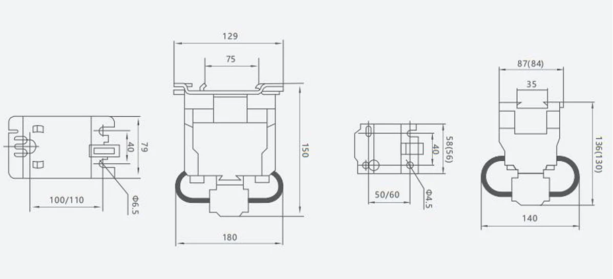
W9’s CJX2 AC contactor listing concerns motor-control applications, while its CJ19 capacitor-duty contactor listing describes capacitor switching. These are different product/application enquiries. A site’s shared category name should not be used to claim identical duty, mounting or dimensions.
- Document the load technology and switching sequence.
- Choose the appropriate utilization category and operational rating.
- Confirm coil supply, contacts, control logic and mounting.
- Verify protection coordination and assembly conditions.
- Retain approved application data and maintenance instructions.
The modular-contactor category can help locate candidates. Request the specific model and its ratings before treating it as suitable for a compact distribution board. Product category membership is not independent certification or cross-brand compatibility evidence.
Frequently asked questions
What does a modular contactor do?
It provides electrically controlled switching in the configuration the manufacturer specifies. It does not automatically provide overload, short-circuit or isolation functions.
Can I select a contactor from amperage alone?
No. Operational voltage, utilization category, inrush, duty cycle and operating environment are also material. Read the current rating in the context of the declared load duty.
Does an LED load need a special check?
Yes. Driver inrush and the supported lighting-duty rating must be assessed. IEC 61095:2023 adds LED-switching requirements including AC-7d, but the exact product’s rating still needs verification.
Is coil voltage the same as the load voltage?
Not necessarily. Specify both supplies separately, including AC/DC and frequency where relevant. Use the actual control schematic and device instructions.
Are all products in a modular-contactor category interchangeable?
No. Duty, mounting, contacts, coil and dimensions vary. An approved replacement needs a complete comparison, not only the category label.
References and conclusion
- IEC 61095:2023 — household and similar contactors; public scope and LED-switching revision.
- IEC 60947-4-1:2023 — industrial contactors and motor-starters, corrected March 2026.
- IEC 61439-1:2020 — assembly general rules, used with the relevant assembly part.
Public references were accessed on 14 October 2026. Specify what the contactor must switch before selecting its size. Contact W9 Group with the load data, switching sequence and control supply for a model-specific enquiry.