
 JCB1-125
 JCB2-40M
 JCB3-63DC
 JCB3-80H
 JCB3-80M
 JCBH-125
 JC80-2P
 JC80-4P
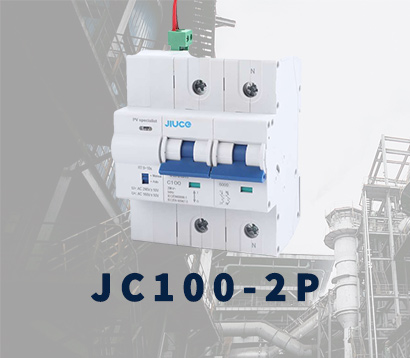 JC125-2P
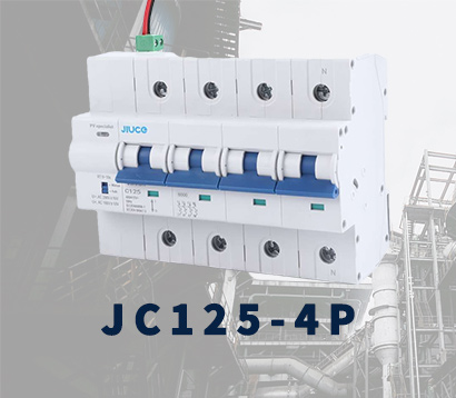 JC125-4P
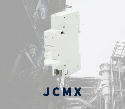 JCMX
JCMX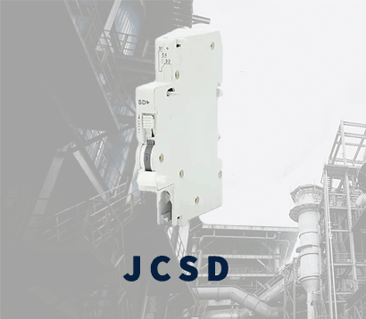 JCSD
JCSD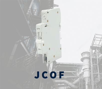 JCOF
JCOF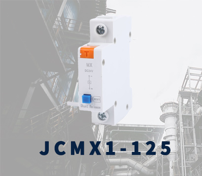 JCMX1-125
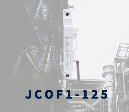 JCOF1-125
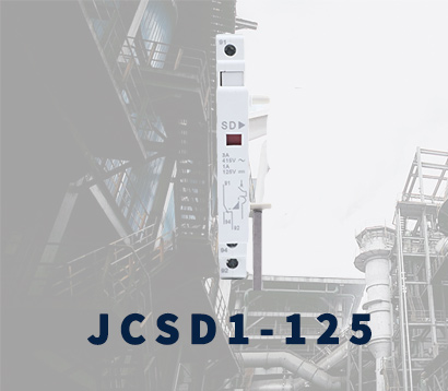 JCSD1-125
 JCRD4-125
 JCRB2-100
 JCR2-63
 JCR1-40
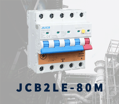 JCB2LE-80M
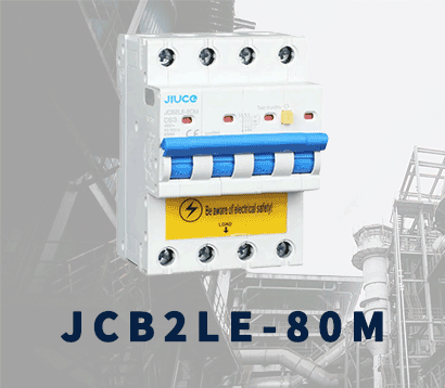 JCB2LE-80M
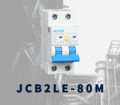 JCB2LE-80M
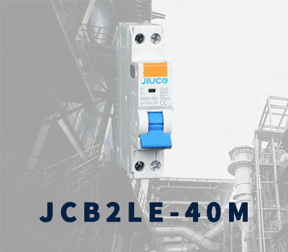 JCB2LE-40M
 JCB1LE-125
 JCB3LM-80
 JCH2-125
 JCH2-125
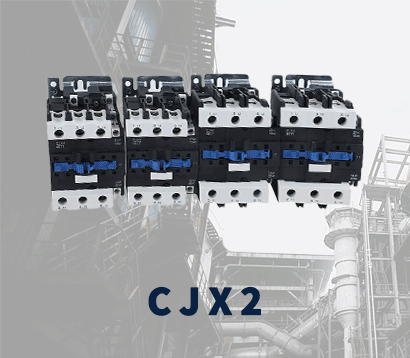 CJX2
CJX2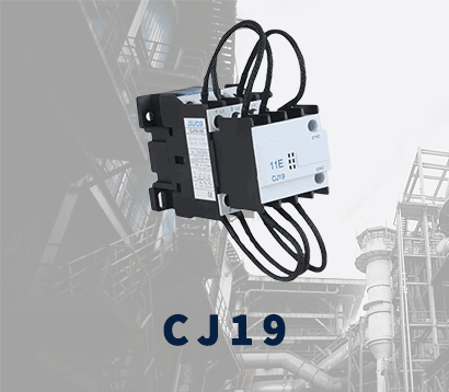 CJ19
CJ19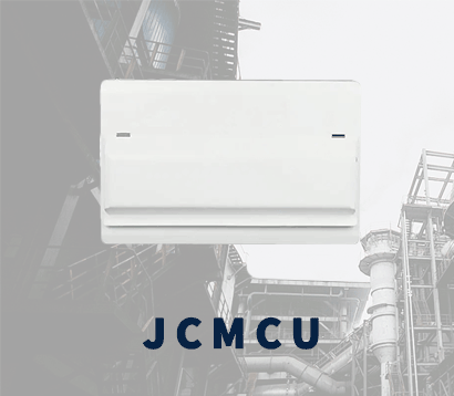 JCMCU
JCMCU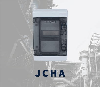 JCHA
JCHA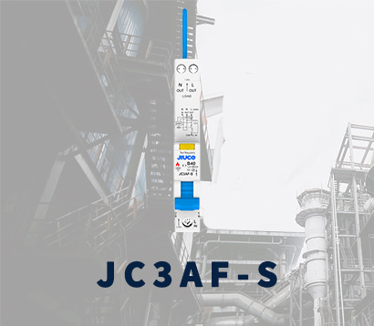 JC3AF-S
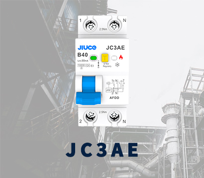 JC3AE
JC3AE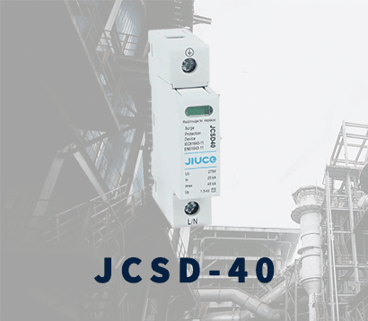 JCSD-40
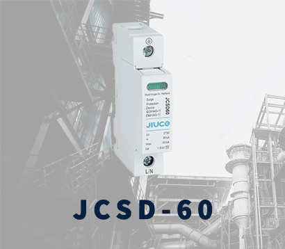 JCSD-60
 JCSP-40
 JCSP-60
 JCSPV
JCSPV WEW1-1000
 WEW1-1600
 WEW1-2000
 WEW1-3200
 WEW1-4000
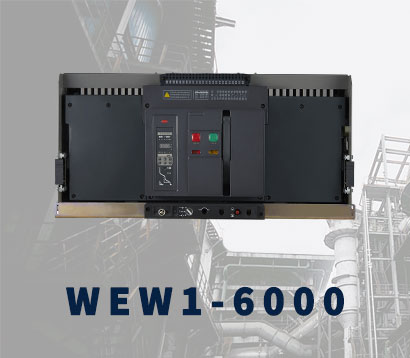 WEW1-6300
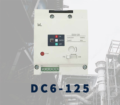 DC6-125
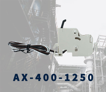 AX-400-1250
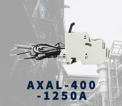 AXAL-400-1250A
 AL-400-1250
 DC3-160
 AXS-400-1250A
 SHT-125-160
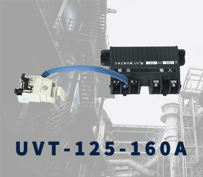 UVT-125-160A
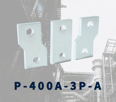 400-3P/4P terminal cover
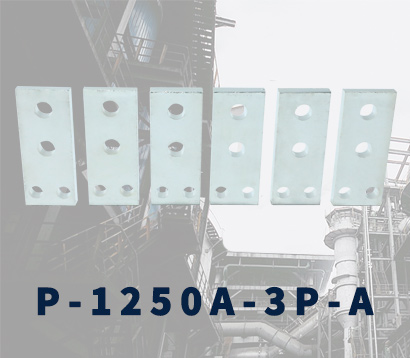 1250-3Pmccb accessories busbar
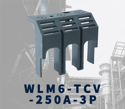 250-3P terminal conver
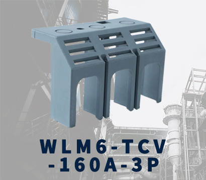 WLM6-TCV-160A-3P
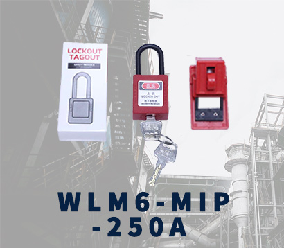 WLM6-MIP-250A
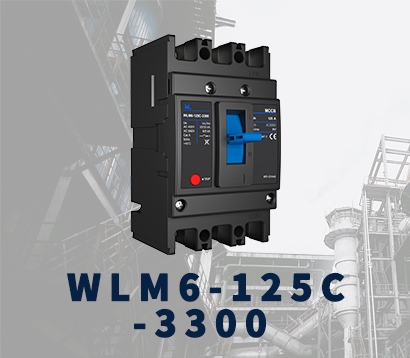 WLM6-125A-3300 3P/4P
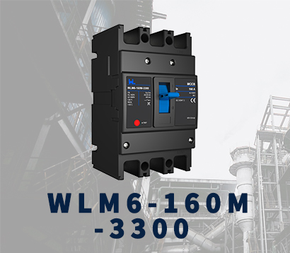 WLM6-160A-3300 3P/4P
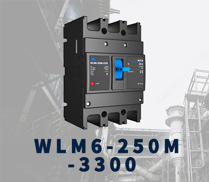 WLM6-250A-3300 3P/4P
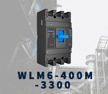 WLM6-400A-3300 3P/4P
 WLM6-630A-3300 3P/4P
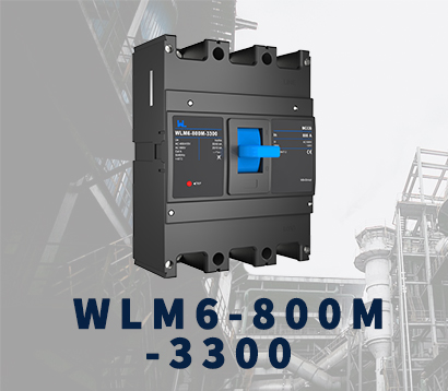 WLM6-800A-3300 3P/4P
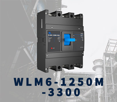 WLM6-1250A-3300 3P/4P
 WLM6-1600A-3300 3P/4P
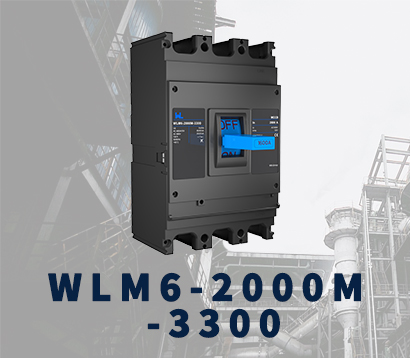 WLM6-2000A 3P/4P
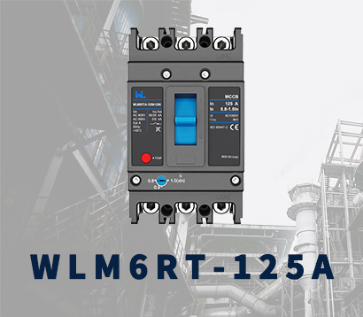 WLM6RT-125A
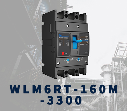 WLM6RT-160A
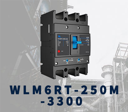 WLM6RT-250A
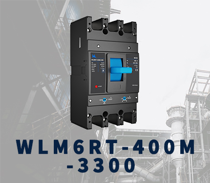 WLM6RT-400A
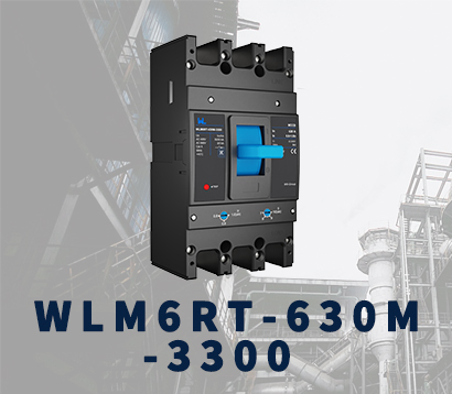 WLM6RT-630A
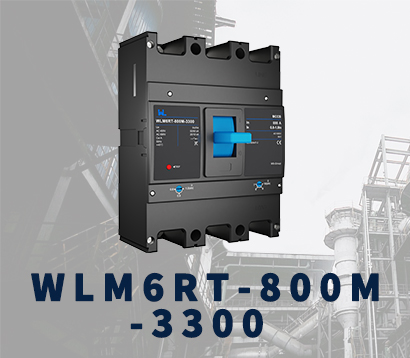 WLM6RT-800A
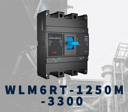 WLM6RT-1250A
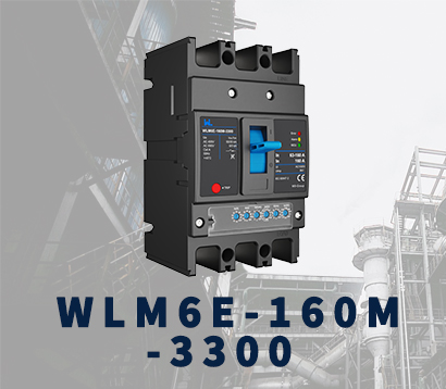 WLM6E-160A-3300 3P
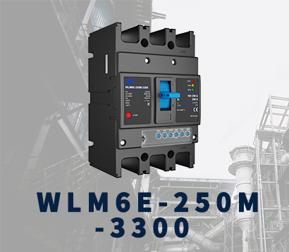 WLM6E-250A-3300
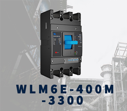 WLM6E-400A-3300 3P/4P
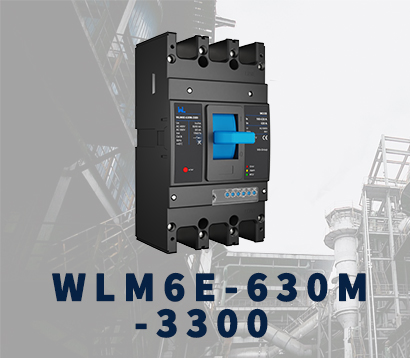 WLM6E-630A-3300
 WLM6E-800A-3300 3P/4P
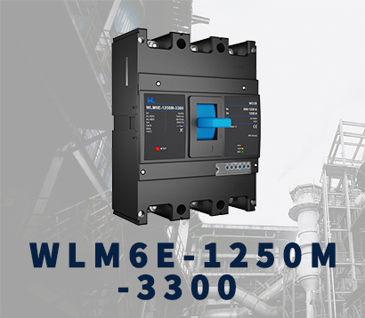 WLM6E-1250A-3300
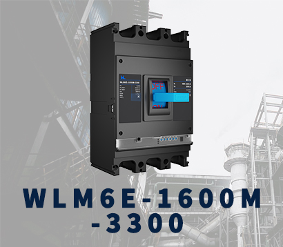 WLM6E-1600-3300 3P/4P
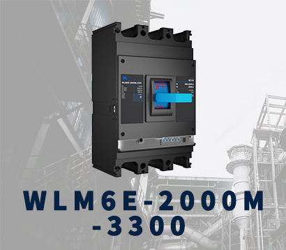 WLM6E-2000A-3300 3P/4P
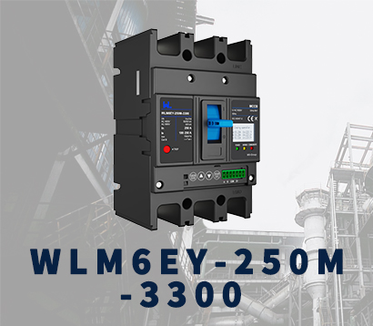 WLM6EY-250-3300 3P/4P
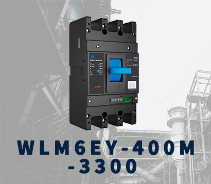 WLM6EY-400 3P/4P
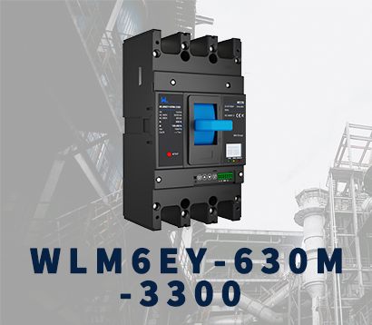 WLM6EY-630 3P/4P
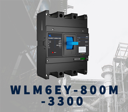 WLM6EY-800A 3P/4P
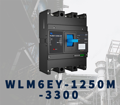 WLM6EY-1250A 3P/4P
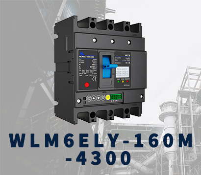 WLM6ELY-160A
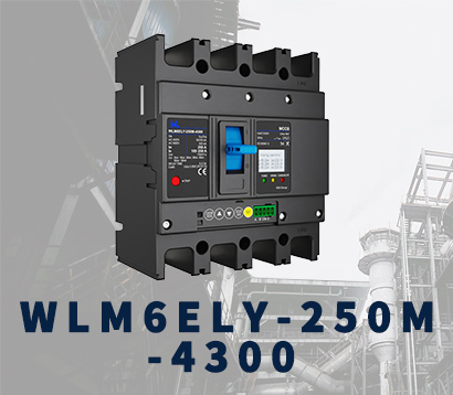 WLM6ELY-250A
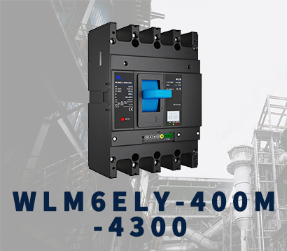 WLM6ELY-400A
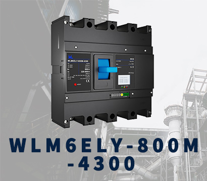 WLM6ELY-800A
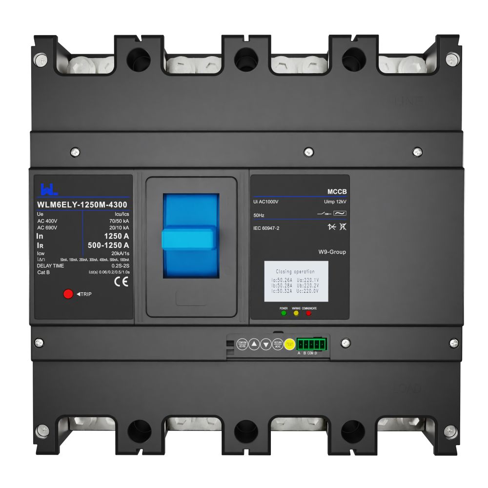 WLM6ELY-1250A
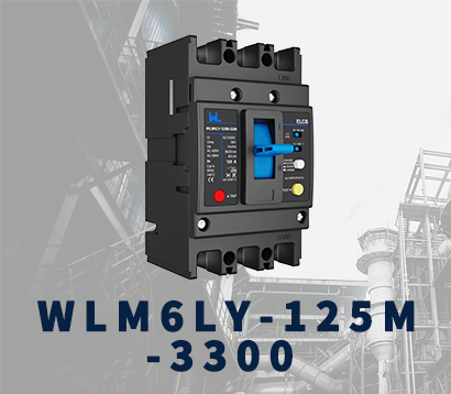 WLM6LY-125A
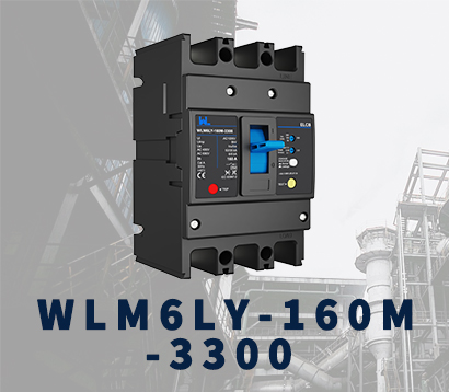 WLM6L-160A
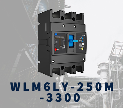 WLM6LY-250A
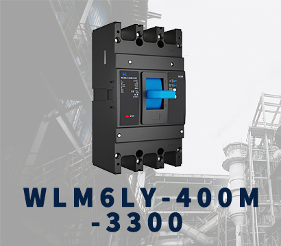 WLM6LY-400A
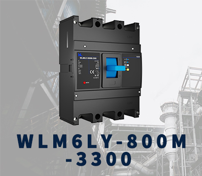 WLM6LY-800A
 WLM6LY-630A
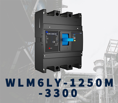 WLM6LY-1250A
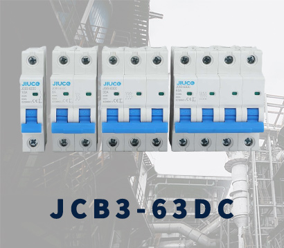 JCB3-63DC
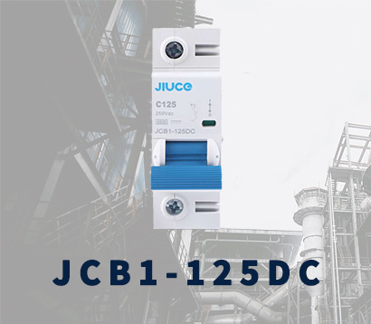 JCB1-125DC
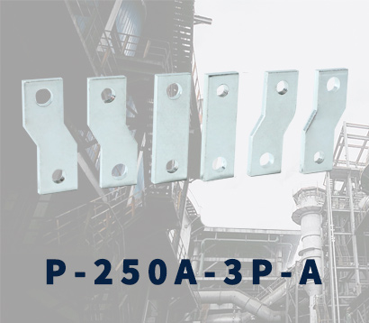 P-250A-3P-A
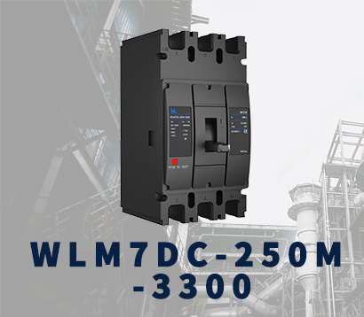 WLM7DC-250A-2300 2P/3P
 WLM7DC-315A-3300 2P/3P
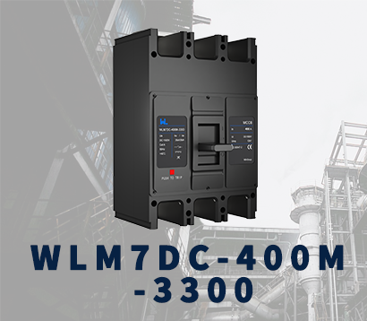 WLM7DC-400A-2300 2P/3P
 WLM7DC-630A-3300 3P
 WLM7DC-800A-2300 2P/3P
 WLM7DC-400A 2300
 WLM7DC-630A-2300 2P
 WLM7HU-250-3300 3P
 WLM7HU-315-3300 3P
 WLM7HU-400-3300 3P
 WLM7HU-630-3300 3P
 WLM7HU-800-3300 3P
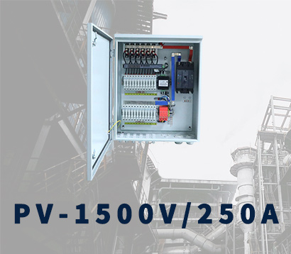 PV-1500V/250A
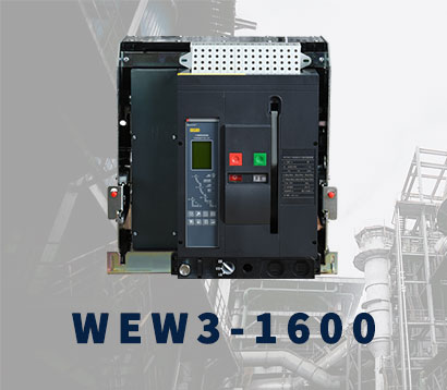 WEW3-1600
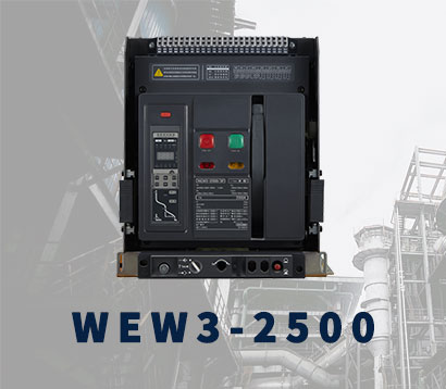 WEW3-2500
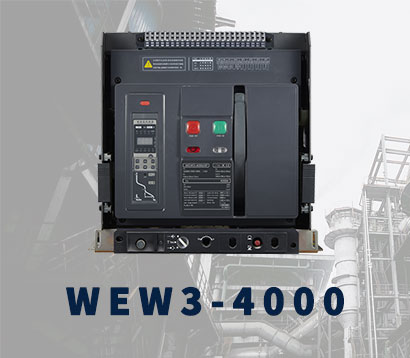 WEW3-4000
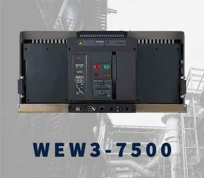 WEW3-7500


MCB Accessories
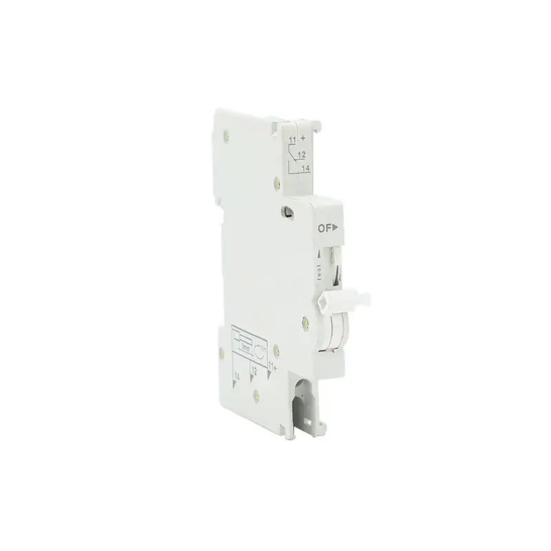
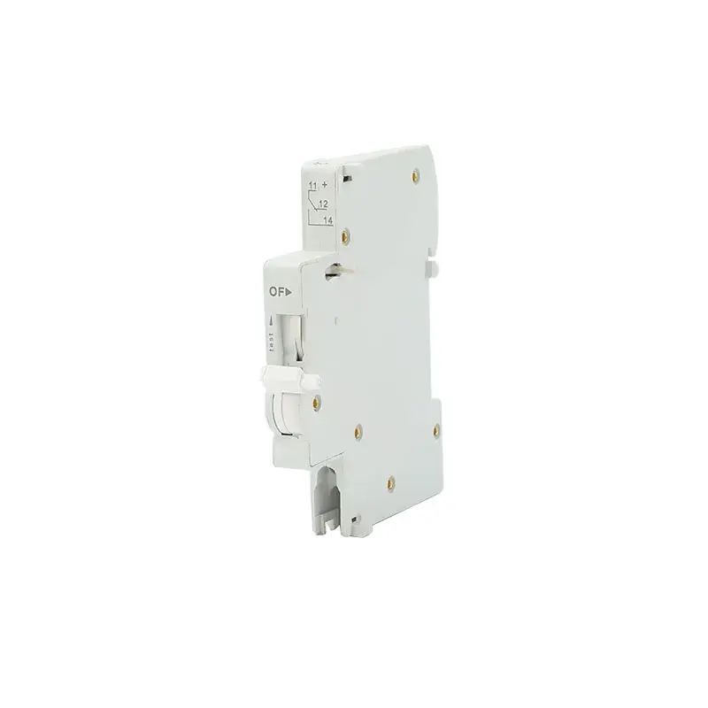
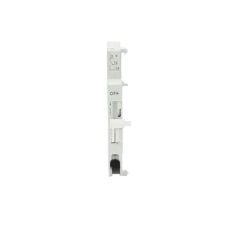
JCOF Auxiliary Contact
Introduction
A JCOF auxiliary contact (or switch) is an auxiliary contact added to a circuit to protect the main contact. This accessory allows you to check the status of your miniature circuit breaker or supplementary protector from a remote location, providing convenience and enhanced monitoring capabilities. Auxiliary contacts facilitate efficient management of electrical systems by remotely determining whether a circuit breaker is open or closed. Furthermore, the functionality of the auxiliary contact goes beyond remote status indication as it plays a vital role in preventing unnecessary power being supplied to the contactor coil in the event of a power circuit failure.
The function of a miniature circuit breaker is to protect the motor by cutting off the power supply in the event of a fault such as a short circuit or overload. However, closer inspection of the control circuit revealed that the connection may have remained closed, causing unnecessary powering of the contactor coil. This is where auxiliary contacts come into play, providing an extra level of control to prevent situations like this from happening.
The function of an auxiliary contact is to allow one switch to control another switch (usually a larger switch). It consists of a coil with two sets of low-current contacts at each end and high-power contacts inside. Contact groups designated as "low voltage" are often identified, clearly indicating their purpose in the circuit. This demonstrates the versatility and importance of auxiliary contacts in ensuring efficient and safe operation of electrical systems.
The auxiliary contacts are similar to the main power contactor coils and are designed to operate continuously throughout the plant and are equipped with a time delay element to prevent arcing and potential damage if the auxiliary contacts open while the main contactor is still energized. This feature ensures the safe and reliable operation of the electrical system.
Auxiliary contacts serve a variety of purposes and are critical to the efficient operation and protection of electrical equipment. They are used to obtain feedback from the main contactor in the event of a trip, providing valuable information for troubleshooting and maintenance. Additionally, auxiliary contacts play a vital role in protecting circuit breakers and other equipment, helping to better protect against electrical damage and reduce the likelihood of electrical failure. By enhancing the durability of circuit breakers, auxiliary contacts help increase the overall reliability and service life of electrical systems, making them an indispensable component in industrial and commercial applications.
Product Description
Main Features
● OF: Auxiliary, it can provide MCB "trip" and "close" status information, providing valuable feedback for the status of circuit protection devices.
● Indicates the location of device contacts for easy monitoring and visual confirmation of MCB operation.
● Special pin design is adopted and installed on the left side of MCB/RCBO to ensure convenient and safe installation while maintaining correct alignment with the circuit protection device.
Difference between the main contact and the auxiliary contact:
| MAIN CONTACT | AUXILIARY CONTACT |
| In an MCB, it is the principal contact mechanism that connects the load to the supply. | Control, indicator, alarm, and feedback circuits use auxiliary contacts, also known as helpful contacts |
| The main contacts are NO (normally open) contacts, which signifies they will only establish contact when the MCB’s magnetic coil is powered. | Both NO (Normally Open) and NC (Normally Closed) contacts are accessible in auxiliary contact |
| Main contact carries high voltage and high current | Auxiliary contact carries low voltage and low current |
| Sparking occurs due to high current | No sparking occurs in auxiliary contact |
| Main contacts are main terminal connection and motor connections | Auxiliary contacts are utilised primarily in control circuits, indication circuits, and feedback circuits. |
Technical Data
| Standard | IEC61009-1 , EN61009-1 | ||
| Electrical features | Rated value | UN(V) | In (A) |
| AC415 50/60Hz | 3 | ||
| AC240 50/60Hz | 6 | ||
| DC130 | 1 | ||
| DC48 | 2 | ||
| DC24 | 6 | ||
| Configurations | 1 N/O+1N/C | ||
| Rated impulse withstand voltage(1.2/50) Uimp (V) | 4000 | ||
| Poles | 1 Pole (9mm Width) | ||
| Insulation voltage Ui (V) | 500 | ||
| Dielectric TEST voltage at ind.Freq.for 1 min (kV) | 2 | ||
| Pollution degree | 2 | ||
| Mechanical features | Electrical life | 6050 | |
| Mechanical life | 10000 | ||
| Protection degree | IP20 | ||
| Ambient temperature (with daily average ≤35℃) | -5...+40 | ||
| Storage temperation (℃) | -25...+70 | ||
| Installation | Terminal connection type | Cable | |
| Terminal size top/bottom for cable | 2.5mm2 / 18-14 AWG | ||
| Tightening torque | 0.8 N*m / 7 In-Ibs. | ||
| Mounting | On DIN rail EN 60715 (35mm) by means of fast clip device | ||


010203040506